Data Flow Modelling in Verilog
The VLSI IC circuits design flow is shown in the figure below. The various levels of design are numbered and the blocks show processes in the design flow.
Ppt Verilog Code For 8 Bit Comparator Powerpoint Presentation Free Download Id 2655445
Multiplexers are used in communication systems to increase the amount of data sent over a network within a certain amount of time and bandwidth.
. A comprehensive resource on Verilog HDL for beginners and experts large and complicated digital circuits can be incorporated into hardware by using Verilog a hardware description language HDL. To help accurately predict these challenging flows we offer a wide range of models for gas liquid solid particle flows and even DEM to get you the most accurate results. Data-modeling business-process modeling - round trip engineering Prosa UML Modeller.
Verilog code for AND gate using data-flow modeling. GDT is very important part of mechanical product design. Module AND_2_data_flow output Y input A B.
Describes how the Vitis development environment lets you build a software application using the OpenCL API to run hardware kernels on accelerator cards like a Xilinx Alveo Data Center accelerator card for FPGA-based acceleration. They also decide on how the data should flow inside the chip. What is meant by GDT.
Specifications comes first they describe abstractly the functionality interface and the architecture of the digital IC circuit to be designed. Yes Yes Open modelbase Yes C Java C SQL DDL and SQL queries C Java and C class headers are synchronized between diagrams and code in real-time Programmers workbenches documentation tools version control systems. Material Data for Simulation.
Besides them assignments using only operators AND NOT sll etc can also be used to construct code. Astronomy chemistry data science earth and planetary science integrative biology mathematics molecular cell biology physics plant microbial biology statistics or any engineering department including EECS. It is also known as a data selector.
Behavioral modeling is the highest level of abstraction in the Verilog HDL. Led by some of our top Senior Traders the program includes option theory systems training trading strategy risk management data analysis quant modeling and hands-on trading simulations. GDT defines degree of accuracy and precision required on controlled feature of part.
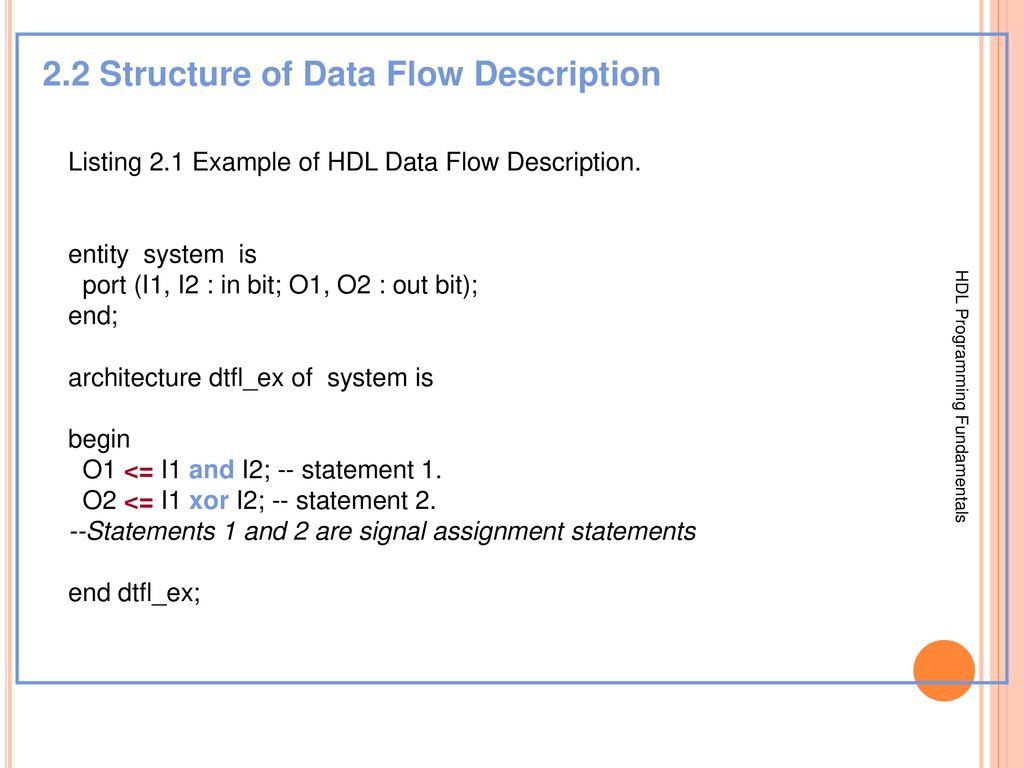
The concurrent statements in VHDL are WHEN and GENERATE. Junior Traders then graduate into real-time trading rotations and a one-on-one mentorship with a Senior Trader. Meanwhile the graphics engine will execute post-processed data from the previous batch dumped into another part of memory and so on.
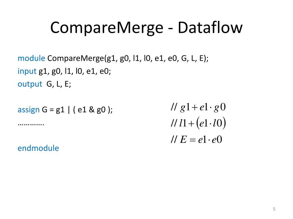
An example would be the data flow when a processor fetches imaging data from the system ram and executes them. Then we use assignment statements in data flow modeling. Different modeling approaches are needed as you move from single to multiphase flow applications and Ansys understands this.
We refer to a multiplexer with the terms MUX and MPX. All that a designer need is the. In this modeling style the flow of data through the entity is expressed using concurrent parallel signal.
Ansys Electronics Desktop AEDT The Ansys Electronics Desktop AEDT is a platform that enables true electronics system design. Week-6Switch level modelling Week-7Synthesis of combinational logic using verilog Week-8Synthesis of sequential logic. Geometric Dimension Tolerance GDT is a system for defining engineering tolerances.
We would again start by declaring the module. AEDT provides access to the Ansys gold-standard electromagnetics simulation solutions such as Ansys HFSS Ansys Maxwell Ansys Q3D Extractor Ansys SIwave and Ansys Icepak using electrical CAD ECAD and mechanical CAD MCAD. A multiplexer is a device that selects one output from multiple inputs.
Students must complete 4 units of Technical Electives chosen from any lower or upper division course in the following departments.

Unit 2 Data Flow Description Ppt Download
Unit 2 Data Flow Description Ppt Download
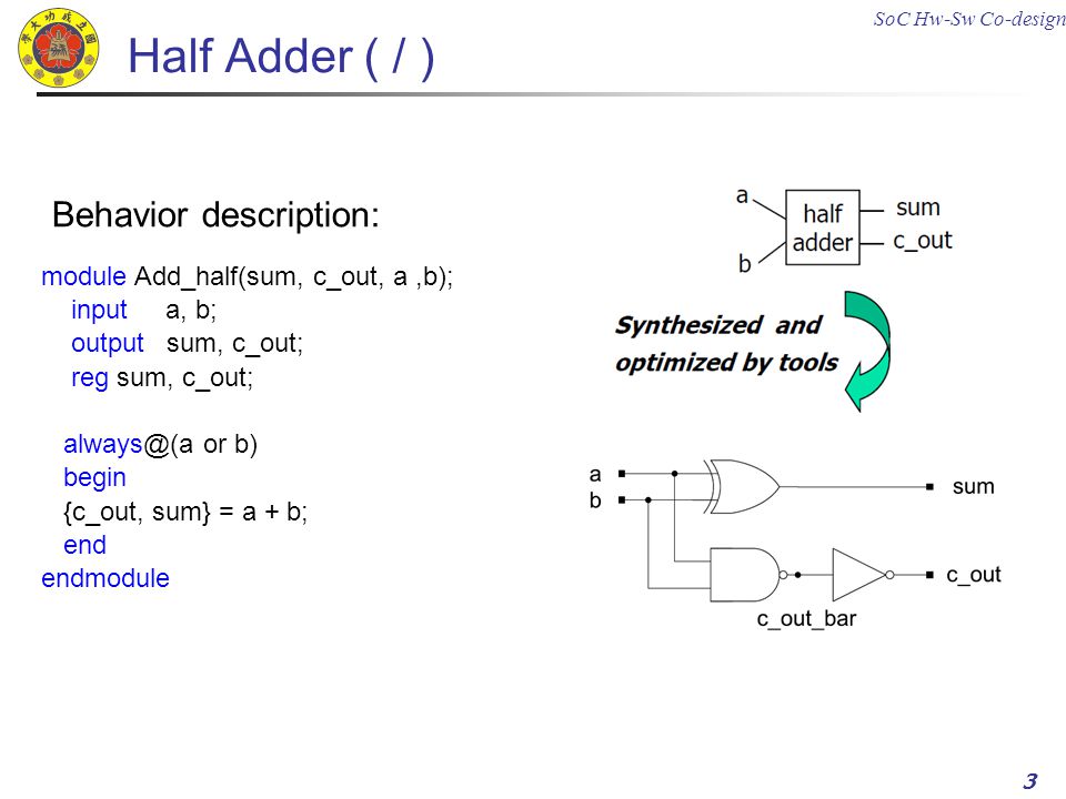
Half Adder Structural Description Data Flow Description Ppt Download
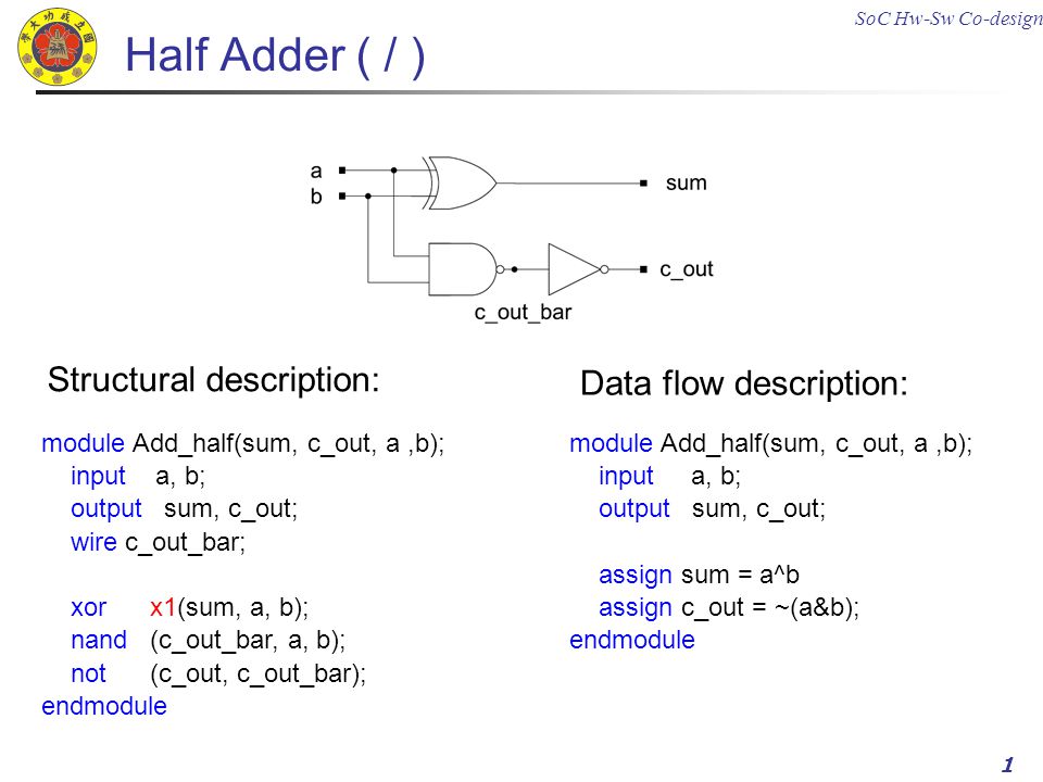
Half Adder Structural Description Data Flow Description Ppt Download
No comments for "Data Flow Modelling in Verilog"
Post a Comment